Drinking water pipes usually operate unnoticed in everyday life. Water is supplied at sufficient pressures, taps are supplied, and technical appliances run in the background. The situation becomes critical when pressure conditions change during maintenance work, pressure fluctuations in the network, negative pressure in a pipe, or incorrectly connected appliances. In such cases, water can flow back against the intended direction of flow.
Backflow preventers in drinking water systems are situated at a sensitive interface between the public supply, domestic plumbing, and downstream appliances. Depending on the installation situation, they protect the upstream network, safeguard individual appliances, isolate specific parts of the system, or form part of a larger safety combination. For planning, installation and operation, the risk of backflow, function, installation location, testability, maintenance, and integration into the pipework system must therefore be clearly defined.
Why backflow can occur in drinking water pipes
Water follows pressure. If the pressure in the supply network drops or a vacuum develops in a pipe, water can be drawn back from a connected installation. If there is higher pressure in a downstream section, water can be forced back. Both scenarios are critical for drinking water installations because contaminated water from connected appliances, technical circuits or incorrectly secured tap points, can enter the drinking water pipes.
Typical triggers include pressure drops in the network, draining operations, pumping processes, maintenance work, incorrect connections, or pipe sections that have been modified at a later date. In existing buildings, for example, refurbishments, heating system replacements, new technical consumers, or subsequently added pipe sections alter the existing interfaces. A heating system fill, a cooling circuit, a dosing station, a laboratory instrument, a cleaning system, or a technical consumer with its own pressure level must then be reclassified.
Backflow preventers: Correctly assessing connection points
A non-return valve or a simple backflow preventer is only suitable if the connection point is appropriate for it. The decisive factors are the type of fluid present in the downstream system, the resulting risk, and the safety device required by the regulations. For drinking water supply systems, it must therefore be clear before installation what function the fitting is intended to perform and whether the connection point requires additional protection.
Of particular importance are connections which appear unremarkable during operation but which, technically speaking, establish contact between drinking water and other media. These include filling valves on heating systems, equipment containing cleaning agents or dosing agents, open containers, process water pipes, or temporary hose connections. Such connections must not place a strain on the drinking water network, either through back-siphonage or back-pressure. For planning and operation, this means that the actual on-site installation is crucial. If a system has been extended, modified, or provisionally supplemented, the backflow prevention must also be reassessed.
Function: What backflow preventers do for drinking water
When open, the valve allows flow to pass through. If water flows in the intended direction, the pressure lifts the closing element or moves it against the spring force. If the pressure or direction of flow changes, the mechanism closes automatically. Depending on the design, the valve disc, spring, seal, cone and housing work together. The flow remains unobstructed as long as the pressure on the inlet side is sufficient. In the event of back pressure or a reversal of flow, the closing element presses against the seat.
This shut-off function serves as a clear hygienic purpose. It prevents water from downstream sections of the pipework, appliances, or technical circuits from flowing back into the drinking water supply. In this way, the backflow preventer protects the intended direction of flow and helps to ensure the quality of the drinking water within the building’s plumbing system, right up to the tap.
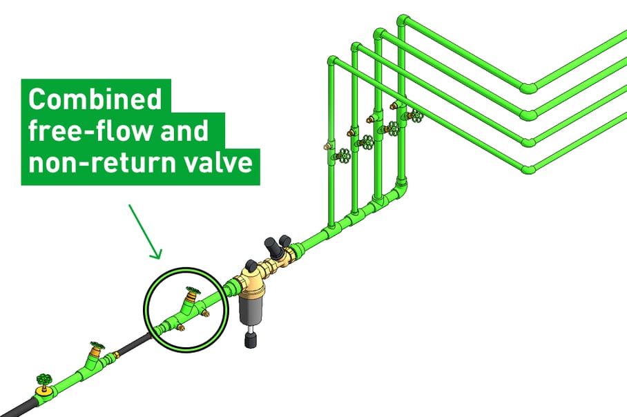
In day-to-day planning, several terms are used for backflow preventers. ‘Non-return valve’ is the more general technical term for a fitting that allows flow in only one direction. ‘KFR’ refers to a ‘combined free-flow valve with backflow preventer,’ as found in many drinking water installations. The term ‘water backflow preventer’ is also frequently used. These refers to the same protective function. However, the precise technical designation should be used for planning, tendering, and documentation.
In plans and bills of quantities, the backflow preventer for drinking water is often abbreviated to RV. For installation and maintenance, however, this abbreviation alone is not sufficient. Particularly in water meter circuits, plant rooms and shafts, the type of fitting, direction of flow, installation position and testing options must be clearly indicated.
A schematic diagram for a backflow preventer in drinking water installations usually places the fitting within the water meter circuit. Upstream and downstream of the component, the shut-off valves, direction of flow and testing options must remain clearly identifiable. The table shows the typical sequence and the respective function of the components.
| Section |
Function in the pipework system
|
| Wasserzähler |
Records the volume of water consumed and often marks the transition to the customer’s installation
|
| Shut-off valve |
Shuts off the section of the pipeline for maintenance, testing or replacement
|
| Backflow preventer or KFR valve |
Ensures the direction of flow and prevents backflow
|
| Inspection port |
Enables the shut-off function to be checked
|
| Downstream drinking water pipe |
Supplies taps, appliances, and other sections of pipework
|
In practice, the water flows from the water meter via the shut-off valve to the backflow preventer or KFR valve, and on into the downstream drinking water pipe. Plans must clearly show the direction of the arrow, the installation position, the water meter run, the shut-off valve, the downstream pipe, and the test point.
When backflow preventers are mandatory in drinking water systems
Backflow prevention is an integral part of the proper installation of drinking water systems. The type of safety device required depends on the connection, the medium, the risk, the pressure conditions, the intended use, and the specifications of the relevant water supplier. A residential building with a water meter circuit, a heating system fills valve, a laboratory connection or a technical consumer with its own pressure level all present different requirements. The safety measure must therefore be tailored to the specific risk. Consequently, the question of when a backflow preventer is mandatory for drinking water can only be answered by considering the specific connection point.
Backflow preventers in the context of regulations and standards
DIN EN 1717 and DIN EN 806 are the European standards for drinking water installations and backflow prevention, which are supplemented in national planning practice by regulations and guidelines. In Germany, the Drinking Water Ordinance (TrinkwV) sets out the legal framework. Section 13 of the TrinkwV requires water supply systems to be planned, constructed, maintained, and operated in accordance with at least the generally accepted rules of technology. For the technical design, standards and regulations governing safety devices for protecting drinking water against contamination caused by backflow, are applied.
The specific connection point is therefore decisive for drinking water hygiene. The medium, the risk, the pressure conditions and the intended use determine whether a backflow preventer is sufficient, or whether another safety device is required, such as a system separator, pipe separator, free outlet, or pipe aerator.
Planning, testing, and maintaining backflow preventers: What matters during operation
With backflow preventers for drinking water, planning, testing, and maintenance are interlinked. The installation location determines whether the direction of flow remains unambiguous, whether shut-off valves are sensibly positioned, whether the test port is accessible, and whether the fitting can be inspected or replaced during operation. Therefore, future maintenance must be considered as early as the pipework planning stage.
This interdependence is evident in plant rooms, shafts, and existing installations. A backflow preventer requires sufficient space, accessible connections and a sequence of components that does not hinder testing and maintenance. Filters, pressure reducers, shut-off valves, adaptors, and the water meter section should therefore not be positioned individually, but should fit together as a functional section of pipework.
Key points for planning and installation:
| Point |
Significance for operation |
| Installation location |
Often in the area behind the water meter or within the water meter circuit, depending on the system and specifications
|
| Flow direction |
Must match the direction of the arrow on the fitting and the actual pipe layout
|
| Installation position |
To be determined according to the manufacturer’s specifications, valve type, and regulations
|
| Surroundings |
Arrange filters, pressure reducers, shut-off valves, and adaptors in a hydraulically sensible manner
|
| Inspection port |
Ensure access for functional checks, leak testing, and maintenance
|
| Accessibility |
Ensure cleaning, replacement and documentation can be carried out during operation
|
Why backflow preventers should be properly documented
Documentation must ensure that the installation location, valve type, direction of flow and test results remain traceable. This is important when operators change, maintenance contracts are re-tendered, or systems are expanded after several years. A clearly labelled water meter circuit with an accessible test port saves time during operation when carrying out checks.
An isometric drawing of the pipework highlights such points prior to installation. It shows pipe lengths, height differences, the sequence of fittings, flow direction, test access points, and maintenance areas in a spatially clear representation. This enables installation errors, unfavourable positions, and subsequent service issues to be identified at an earlier stage.
From the backflow preventer to the appropriate pipework system
A fitting may be selected correctly from a technical point of view but still cause problems during operation if the connection type, pressure loss, installation position, or accessibility to the system do not suit the specific installation situation. Backflow preventers for drinking water, pipework, fittings, transitions, water meter runs, filters, pressure reducers and maintenance areas must be coordinated in terms of hydraulics, structural design, and maintenance requirements.
Factors to consider when selecting a system include:
- Nominal diameter and pressure range
- Temperature and medium
- Material and connection type
- Permissible installation position
- Approval for drinking water
- Pressure drop and hydraulic effect
- Testability and documentation
- Accessibility during subsequent operation
Pipe classes are also part of this assessment, as they define pressure and temperature ranges, wall thicknesses, SDR ratios and service limits. In practice, this concerns the coordination between pipes, fittings, valves, adaptors, and operating parameters. In mixed installations, further questions arise: Which components are made of plastic, stainless steel, or brass? How are metallic valves integrated? Which sealing elements are suitable for the medium? Which manufacturer’s specifications apply to adaptors for third-party systems?
Conclusion: Prevent backflow and operate drinking water systems safely
Backflow preventers are essential for minimising risks in a drinking water system. They safeguard the direction of flow and therefore the integrity of the system at its most sensitive points: at junctions, extensions, technical consumers, and interfaces with other media. It is at these points that the hygiene of the drinking water is ensured right up to the point of use.
For operators and planners, this means that backflow prevention must be incorporated into the early planning stages of the pipework system, fittings, water meter circuit and technical connections. This results in systems that are professionally secured, remain traceable during operation and allow for subsequent modifications without compromising hygiene.
Talk to our experts
aquatherm supports you in the planning and implementation of suitable pipework systems for drinking water. Talk to our experts about your project plans.

.jpg)